
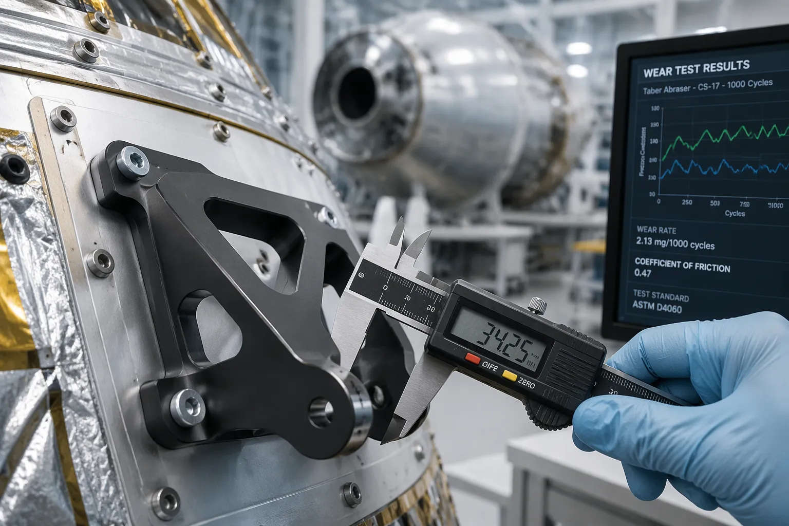
Hard anodizing transforms the aluminum surface into a dense aluminum oxide layer. This layer resists wear far beyond bare metal. Aerospace components face sliding, galling, and erosion. Untreated aluminum cannot survive these forces. Type III hard anodizing delivers surface hardness up to 60–70 HRC and thickness of 0.001–0.003 inches. The oxide layer is integral to the substrate, so it will not chip or flake like applied coatings. Correct alloy selection and process control determine whether a part meets aerospace wear requirements. For US industrial buyers and aerospace component engineers, Qingdao Xuxiangtai provides aluminum component wear protection for demanding aerospace applications.
Key Takeaways
- Hard anodizing creates a super hard ceramic layer on aluminum. This layer resists wear and corrosion for aerospace parts.
- Choose the right aluminum alloy like 7075-T6 for maximum hardness. Use Type III anodizing for severe wear conditions.
- Follow design rules to avoid defects. Proper planning ensures parts meet specifications and last longer.
The Science Behind Hard Anodizing for Aluminum Component Wear Protection
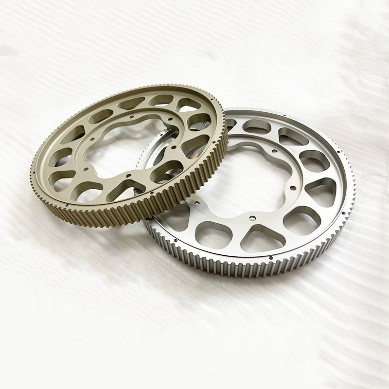
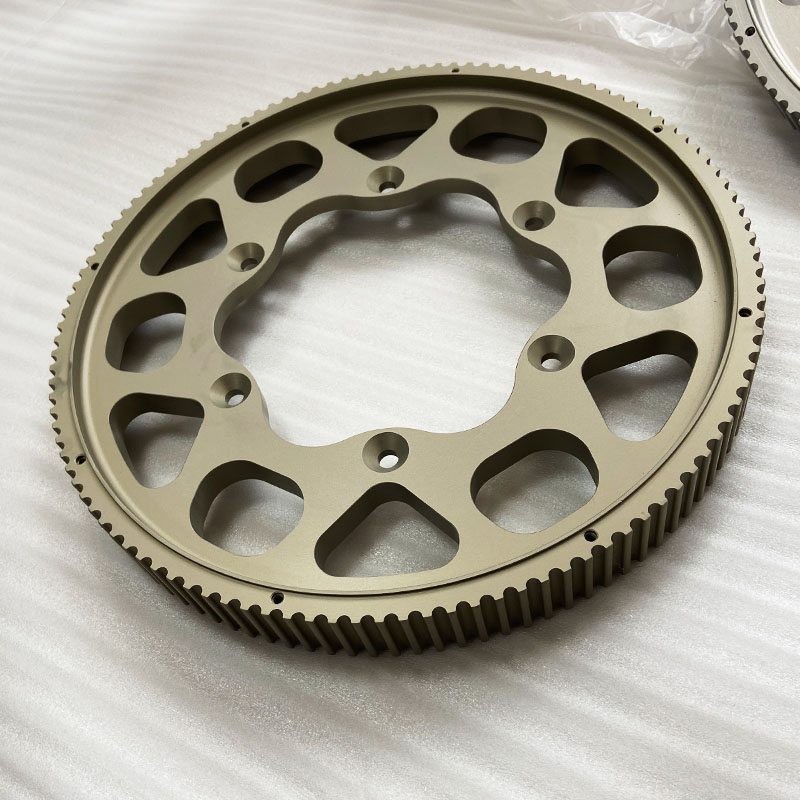
Hard anodizing relies on electrochemistry to transform an aluminum surface into a durable oxide layer. Understanding this science helps engineers specify the right process parameters for aerospace components. Qingdao Xuxiangtai applies these principles to deliver aluminum component wear protection for demanding applications.
How the Anodic Oxide Layer Forms
The formation of an anodic oxide layer begins with surface reconstruction. Chemisorption occurs at preferred nucleation sites on the aluminum surface. This step precedes oxidation. Thermodynamics at the aluminum surface favor only aluminum oxidation. Alloying elements and contaminants can retard reaction kinetics. During early oxide growth, lateral film growth after surface reconstruction produces a columnar structure. This structure forms instead of selective oxide dissolution. Infant oxide flakes impinge on one another. Repulsive forces between similarly charged oxide flakes drive outward growth. Pores form through repulsive field effects on the inside surfaces of the flakes. Mass transport of the forming hydrated aluminum oxide network across column outer walls knits the structure together. The integrity of these knitlines strongly influences the final film's mechanical and chemical robustness. Only aluminum and oxygen react to form the finish. Other alloying elements and atomic-level defects such as dislocations and vacancies are entrained at the substrate interface. These defects transport with oxide flakes during lateral growth. Pore wall reactivity also enables adsorption of electrolyte counter ions, additives, and seals. The reactivity or passivity of adsorbed counter ions controls film thickness. Reactive counter ions facilitate charge transfer along the inside surface of the oxide flake. This promotes oxidation, pore formation, and outward columnar growth. Passive counter ions such as chromate do not facilitate charge transfer. Would-be columns collapse and produce a coarse, disordered Type I nanostructure. In Type III hard anodizing, lower process temperature reduces the initial number of oxide nucleation points during surface reconstruction. Increased current density increases both column thickness and pore diameter. This yields fewer columns with coarser walls up to about 50 μm thick.
The electrolytic process follows a defined sequence:
- The aluminum object serves as the anode and a carbon electrode as the opposing pole in an electrolyte bath under DC current.
- Surface aluminum dissolves and binds with oxygen to create an aluminum oxide surface layer, called the anodic oxide layer.
- In acid solution electrolysis, oxygen emitted at the aluminum anode immediately binds with dissolved surface-layer metal before gasifying, forming aluminum oxide.
- A barrier layer forms during the initial phase of electrolysis.
- The process advances to formation of a porous layer, which grows to a certain thickness.
- The resulting anodized layer consists of an electrically conductive but non-growing barrier layer and an isolating but growing porous layer.
- The oxygen produced at the anode creates a porous layer with electrical isolation, corrosion resistance, and wear resistance, and the porosity can be used for coloring and added functions.
Why Hardness and Wear Resistance Increase
The hardness of the anodic oxide layer comes from its ceramic-like aluminum oxide structure. This oxide layer is significantly harder than the base aluminum material. Hard anodizing produces an aluminum oxide layer that offers remarkable wear resistance. The table below compares hardness values for common surface treatments.
| Surface Treatment | Hardness Range (HV) |
|---|---|
| Hard Chrome Plating | 850–1000 HV |
| Hard Anodizing | 300–600 HV |
Hard chrome plating is noted for its exceptional hardness. Chrome-plated surfaces are significantly harder than the base material and provide outstanding resistance to wear, abrasion, and damage. In comparison, hard anodizing produces an aluminum oxide layer that is significantly harder than the base aluminum material. It offers remarkable wear resistance, though its hardness is generally lower than that of hard chrome plating. The columnar structure of the oxide layer contributes to its wear resistance. The knitlines between columns provide mechanical integrity. A denser columnar structure resists sliding and galling forces better. Aerospace components benefit from this structure because they face repeated sliding contact. The oxide layer also maintains its hardness at elevated temperatures. This property suits hydraulic components and actuators that generate heat during operation.
Corrosion Protection Mechanisms
Hard anodizing provides a thicker and harder oxide layer than standard anodizing. This makes it suitable for demanding mechanical environments such as sliding and wear surfaces, hydraulic components, and repeated abrasion. The protection extends beyond just cosmetic or light-duty corrosion resistance. Several mechanisms work together to protect the aluminum substrate.
- Chemically stable Al₂O₃ film: The aluminum oxide (Al₂O₃) layer formed by hard anodizing is chemically stable. Once sealed, it resists moisture, salts, and most chemical media. As an amphoteric oxide, it can dissolve in strong acids or strong bases.
- Barrier layer: A thin, dense, non-porous layer (about 0.01–0.1 μm) adjacent to the aluminum substrate forms the foundation of corrosion resistance and electrical insulation.
- Increased film thickness: Anodizing can grow the oxide film to several micrometers or even hundreds of micrometers, boosting protective capability by hundreds or thousands of times.
- Base metal integration (no peeling): The film grows from within the substrate with no bonding interface, so it will not age, peel, or delaminate, even under thermal stress (>80°C) that causes micro-cracking.
- Easy to clean and maintain: After sealing, the surface is highly chemically inert, resisting dirt and standard cleaners, which reduces maintenance for outdoor applications.
These mechanisms combine to deliver reliable performance in saltwater exposure, hydraulic fluid contact, and industrial environments. The barrier layer provides the first line of defense against corrosive attack. The porous layer, once sealed, adds another level of protection. The integral growth of the oxide layer ensures that corrosion protection remains intact throughout the component's service life.
Aluminum Grades for Hard Anodizing
Alloy selection determines whether a hard anodized coating achieves the required wear performance. The metallurgical composition of each aluminum grade directly influences oxide layer formation, density, and hardness. Engineers must match the substrate to the application demands.
Best Alloys: 6061, 7075, and 2024
The 6000 and 7000 series alloys dominate aerospace hard anodizing applications. Alloying elements such as copper, silicon, and zinc affect the uniformity and density of the aluminum oxide layer. The 7000 series alloys containing zinc produce harder, more wear-resistant coatings compared to 6000 series alloys. The table below summarizes performance data for common aerospace alloys.
| Alloy | Coating Thickness | Typical Hardness (HRC) | Abrasion Resistance |
|---|---|---|---|
| 6061-T6 | 50 µm | 45–50 | Good |
| 6061-T6 | 75 µm | 48–55 | Good (may become brittle) |
| 7075-T6 | 50 µm | 60–70 | Excellent |
| 7075-T6 | 75 µm | 65–72 | Excellent (higher risk of cracking) |
For 6061 aluminum, optimal process parameters include sulfuric acid concentration of 190 g/L, electrolyte temperature of -2 °C, current density of 4.4 A/dm², and 60-minute duration. These conditions maximize microhardness at 679 HV with 59 μm thickness.
Alloys That Anodize Poorly
High-copper alloys such as the 2000 series are difficult to hardcoat effectively. They tend to yield softer, less protective layers. Zinc and manganese alloys may not be suitable for anodizing. Copper, magnesium, and silicon alloys are well-suited for aerospace applications.
Matching Grade to Aerospace Application
Aerospace engineers select alloys based on specific wear requirements. The 7075-T6 grade suits high-wear surfaces requiring maximum hardness. The 6061-T6 grade works well for general-purpose components needing balanced performance. The 2024 alloy serves applications where weight reduction outweighs maximum wear resistance.
Type II vs. Type III Anodizing
Aerospace engineers face a critical decision when specifying anodizing for aluminum components. Type II and Type III anodizing both create an aluminum oxide layer on the substrate. The two processes differ significantly in coating thickness, hardness, and application suitability. Understanding these differences ensures the right specification for each aerospace component.
Coating Thickness and Hardness Differences
Type II anodizing produces a thinner oxide layer. This layer provides scratch resistance and corrosion resistance for general applications. Type III anodizing yields a much thicker and denser oxide layer. The denser structure results in improved hardness, abrasion resistance, and dielectric properties. The table below compares the key properties of both anodizing types.
| Property | Type II Anodizing | Type III Anodizing |
|---|---|---|
| Coating thickness | 0.0002"–0.0008" | Nominal 0.002" (unless drawing specifies otherwise) |
| Hardness | Resists scuffing and handling wear | 400–530 HV (Gleco process: 500–530 VPN on common alloys) |
| Process conditions | Standard bath temperature and current density | Lower bath temperature, higher current density |
| Wear resistance | Moderate | Approximately 10× more wear-resistant in Taber abrasion testing |
The hardness difference between the two types has practical implications for aerospace components. Type II anodize reaches 300–400 HV, which is roughly equivalent to soft steel. This hardness level provides decent scratch resistance against fingernails and plastic. However, Type II coatings gouge easily under metal-on-metal contact. Type III hardcoat reaches 900–1100 HV, which approaches 60–70 HRC. This hardness level suits severe abrasive and wear applications. Engineers use Vickers Microhardness (HV) for measurement because a Rockwell C macro-indenter would punch through the thin ceramic coating and measure the soft aluminum substrate. This would give a false low reading.
The process conditions drive these property differences. Type II anodizing uses standard bath temperature and current density. Type III anodizing requires lower bath temperature and higher current density. These conditions produce a denser, thicker oxide layer. The denser structure delivers superior wear performance for demanding aerospace applications.
When to Specify Type II
Type II anodizing suits aerospace components that need corrosion protection and moderate wear resistance. This specification works well for parts that do not face severe abrasive contact. Engineers specify Type II for interior panels, housings, brackets, and non-structural components. These parts benefit from the protective oxide layer without requiring maximum hardness.
Type II anodizing also provides electrical insulation. The process creates a dielectric property on the aluminum surface. This makes Type II suitable for aerospace components where electrical conductivity must be avoided. Engineers can specify Type IIB for applications requiring a thinner coating. This variant offers Type II benefits with reduced thickness. It serves as a replacement for Type 1C anodizing. Class 2 Type II anodizing delivers the same durability as clear anodizing (Class 1) while adding a dyed finish. This option comes in red and black for aerospace components requiring both protection and visual distinction.
Several specifications govern Type II anodizing in aerospace applications. AMS-2471 delivers consistent results under strict aerospace standards. This specification enhances corrosion resistance and wear protection. MIL-PRF-8625 meets strict performance requirements for military and aerospace applications. It provides surface durability and corrosion protection for extreme operational environments. These specifications ensure that Type II coatings meet the demanding requirements of aerospace service.
When Type III Is Required
Type III hard anodizing becomes necessary when aerospace components face severe wear conditions. Landing gear, engine components, and structural parts often require this specification. These components endure repeated friction, abrasive contact, and corrosive exposure during service. Type III anodizing improves durability and corrosion resistance under these demanding conditions.
Hydraulic systems represent a critical application for Type III hard anodizing. Pistons, cylinders, and actuator components face continuous sliding contact. The hard oxide layer resists galling and wear that would destroy untreated aluminum. Aircraft landing gear also benefits from Type III anodizing. These components face impact loads, abrasion from runway debris, and exposure to harsh weather. The hard anodized surface maintains its integrity through thousands of landing cycles.
For critical aerospace applications in demanding environments, Type III hardcoat anodizing with Teflon impregnation offers additional advantages. This process produces a self-lubricating oxide layer highly resistant to wear, abrasion, and corrosion. The Teflon impregnation fills the pores of the oxide layer. This reduces friction and provides dry lubrication for components where traditional lubricants may not survive. The self-lubricating property suits aerospace wear conditions where repeated friction, abrasive contact, and corrosive exposure are present.
The decision between Type II and Type III ultimately depends on the specific wear requirements of each component. Type II provides adequate protection for many aerospace applications. Type III delivers the hardness and thickness needed for the most demanding wear environments. Engineers who match the anodizing type to the application achieve optimal performance and service life.
The Hard Anodizing Process Step by Step
Hard anodizing follows a controlled sequence that determines coating quality. Each stage prepares the aluminum surface for the next. Process engineers monitor every step to ensure consistent results.
Pre-Treatment and Cleaning
Pre-treatment removes contaminants and prepares the aluminum surface for oxide growth. A clean surface ensures uniform coating formation. The process follows these steps:
- Cleaning removes machining residuals, grease, and fingerprints using a mild non-corrosive solution.
- Etching removes die lines, surface defects, and the naturally formed oxide layer, typically with an alkaline process.
- Desmutting removes black smut formed by alloying elements during etching.
- Rinsing between each step prevents contamination carryover and anodizing defects.
Technicians verify a water-break-free surface before proceeding. This confirms the surface is ready for uniform oxide formation.
Anodizing Bath Parameters
Bath parameters directly influence coating hardness, thickness, and wear resistance. The table below summarizes typical operating ranges.
| Parameter | Value/Range |
|---|---|
| Sulfuric acid concentration | 180–333.91 g/L |
| Current density | 2.5–5 A/dm² |
| Temperature | 0–5 °C |
| Voltage | 240–360 V |
| Time | 15–40 min |
Lower electrolyte temperatures reduce chemical dissolution and yield more uniform microstructures with higher hardness. Sulfuric acid concentration shows maximum effect around 190 g/L for both thickness and microhardness. Anodizing duration correlates nearly linearly with film thickness until formation and dissolution rates equalize.
Sealing and Post-Treatment
Sealing closes the pores of the oxide layer and enhances corrosion resistance. Several methods serve different aerospace requirements.
- Hydrothermal sealing in boiling deionized water converts oxyhydroxide to aluminum trihydroxide, which closes the pores.
- Chromate sealing forms aluminum oxydichromate or oxychromate depending on pH.
- Ambient-temperature nickel fluoride sealing precipitates nickel hydroxide to block pore mouths.
- Teflon sealing improves lubricity for wear-critical components.
Unsealed or partially sealed coatings suit applications requiring adhesive bonding or enhanced lubrication. These coatings absorb contaminants easily, so they require limited storage and special packaging.
Industry Standards and Specifications
Aerospace hard anodizing follows strict specifications that govern coating thickness, hardness, and corrosion performance. These standards ensure consistent results across production runs and suppliers.
MIL-A-8625 Type III Requirements
MIL-A-8625 defines the core requirements for Type III hard anodizing. The specification covers thickness, hardness, corrosion resistance, and process conditions.
| Requirement | Specification |
|---|---|
| Thickness | 0.0005 to 0.004 inches |
| Hardness | Very high, suitable for abrasion resistance |
| Corrosion Resistance | Excellent, even in harsh conditions |
| Applications | Military and industrial components exposed to extreme wear |
| Process Conditions | Lower temperatures and higher current densities |
The process maintains electrolyte bath temperature between 68°F to 72°F. Current density typically ranges from 12 to 25 amperes per square foot. Longer anodizing times produce thicker films.
An example of a hard anodized and black dyed finish designated by this specification would be: MIL-A-8625 (latest version), Type III, Class 2 black, 2.0 mil coating thickness.
Mil-A-8625 requires 2 mils +/- .0004. Note that the coating both penetrates the surface and builds from the surface in roughly 50% proportions.
AMS 2469 and Related Specs
AMS 2469 serves as the aerospace industry standard for hard coat anodize. The specification requires a coating thickness of 0.0020 inch ± 0.0005. Four tests are specified: thickness, coating weight, color, and quality. Sealing for improved corrosion resistance is optional and must be specified by the customer.
Related specifications include:
- Mil-A-8625 Type III, Class 1 & 2
- MIL-STD 171 7.5.1
- MIL-STD 171 7.5.2
- AMS 2468 & 2469
- BS 5599
- BS EN 2536
- ASTM B 580 Type A
- BAC 5821
- PS 13208
- PS 13201
- PS 13021.1
- HP 4-79
Testing and Quality Verification
Quality verification employs multiple test methods to confirm coating performance. Eddy current devices measure coating thickness easily, with hardcoat typically being 40 to 60 µm thick. Vickers microhardness testing provides hardness values ranging from 300 to 600 HV. The Taber Abraser measures coating weight loss in a standardized wear test.
| Requirement | Typical Specification | Test Method |
|---|---|---|
| Coating Thickness | 0.002" ± 0.0002" | ASTM B244 (eddy current) |
| Coating Weight | Varies by alloy | ASTM B137 |
| Corrosion Resistance | 336 hours (unsealed) | ASTM B117 Salt Spray |
| Sealing Quality | Pass/Fail (acid dissolution) | ASTM B680 |
| Hardness / Wear Resistance | Not a direct Rockwell value; quantified by wear resistance | Taber Abrasion Test |
Additional verification methods include visual inspection, dye fastness testing for colored anodizing, adhesion testing per ASTM D3359, and electrochemical impedance spectroscopy for corrosion resistance and coating uniformity.
Design Guidelines for Manufacturability
Engineers who plan for hard anodizing during the design phase avoid costly rework and assembly problems. The oxide layer grows both inward and outward, so every coated surface changes dimension. Proper planning ensures parts meet final print specifications.
Dimensional Growth and Tolerance Planning
Hard anodizing adds roughly half the coating thickness to external surfaces. A 10.000 mm shaft with 0.010 mm growth per surface finishes near 10.020 mm. A 10.050 mm bore finishes near 10.030 mm. The table below summarizes typical dimensional effects.
| Feature | Approximate Dimensional Effect |
|---|---|
| One coated external surface | +0.5 × coating thickness |
| Outside diameter (two surfaces) | +1 × coating thickness |
| Bore diameter (two walls) | −1 × coating thickness |
| 60° thread pitch diameter | ~2 × coating thickness |
For hard anodizing, NASA describes a typical split: approximately half penetrates the original surface, while half grows outward. Treat the half-thickness relationship as an estimate, rather than a guaranteed allowance. (NASA PRC-5006 Rev. D)
Engineers should state whether drawing dimensions apply before or after anodizing. For finished dimensions, provide a controlled pre-finish table linked to the processor's qualified growth data.
Edge, Corner, and Thread Considerations
Sharp edges create thin, burned coating during Type III hard anodizing. A minimum radius of approximately 0.76 mm allows uniform coating formation. Rounded corners anodize more predictably than sharp geometry.
Threaded features require special attention. Coating builds on thread flanks, reducing engagement and risking interference. Engineers should mask threaded holes or machine threads after anodizing. If threading before anodize, open holes by 0.002–0.003 inches per surface for Type III.
Masking and Contact Points
Masking protects critical areas from coating buildup. Tapes, lacquers, and plugs shield threaded holes, sealing faces, and tight-tolerance features. The process involves cleaning, material selection, precise application, removal, and final inspection.
Every part requires at least one conductive contact point for current flow. Rack marks remain uncoated and are unavoidable. Engineers should designate hidden or non-critical surfaces for contact points. Flat parts can clamp along edges. Cylindrical parts may suspend through the bore. Adequate contact area ensures proper current density and consistent coating.
Common Defects and Solutions
Hard anodizing defects fall into predictable categories. Process engineers who recognize the warning signs correct them before they affect production runs.
Burning and Edge Effects
Burning appears as black or dark areas surrounded by bright, soft, or absent oxide. Excessive local current density combined with insufficient electrolyte agitation causes this defect. Poor electrical contact between the rack and the aluminum part also concentrates current into a small area and generates intense heat. The table below summarizes corrective actions.
| Aspect | Details |
|---|---|
| Appearance | Black or dark areas surrounded by bright, soft, or absent oxide |
| Causes | Excessive local current density; insufficient agitation; poor rack contact |
| Corrective actions | Reduce current density to 1.2–1.5 A/dm² for Type II; improve electrolyte agitation |
Burning is not actual ignition. It results from using higher current than the process supports. Electricity follows the path of least resistance, so burning often occurs at corners. Slow voltage ramp-up is essential because the anodized film limits excessive current. Parts with poor contact are especially vulnerable. In hard anodizing, high voltage and high current generate substantial heat, so excellent agitation directly at the part is necessary.
Poor Adhesion and Chalking
Poor adhesion and chalking typically stem from inadequate sealing or contaminated surfaces. Chalking occurs when the oxide layer remains unsealed and absorbs moisture or chemicals. The surface then develops a powdery white residue. Proper sealing closes the pores and prevents this condition. Contamination from oils, fingerprints, or machining residue also weakens the oxide layer. Strict pre-treatment and clean handling prevent these defects.
Inconsistent Thickness
Uneven anodized color often indicates uneven oxide thickness. Inconsistent current distribution or inadequate surface preparation causes this problem. Light and dark patches on the coated surface suggest uneven coating deposition. Several factors lead to inconsistent thickness, and each requires specific control methods.
- Tank chemistry and temperature variation require tight control of concentrations and temperature.
- Running by voltage instead of current density causes variation; run loads by current density (amps per square foot).
- Insufficient racking or bussing current-carrying capacity limits uniform coating; ensure adequate electrical capacity.
- Improper cathode placement and anode-to-cathode ratio require optimization.
- Part geometry, especially blind holes, needs auxiliary cathodes or plugging.
- Mixed alloys in a lot etch and coat differently; verify alloy consistency.
- Surface preparation variability affects results; control etching and note critical dimensions.
Design engineers should note that surface preparation of aluminum, more so than most other metals, can be subject to greater dimensionality changes.
Aerospace Application Examples
Pistons and Hydraulic Components
Hard anodizing serves critical roles in aerospace pistons and hydraulic systems. The process creates a dense aluminum oxide layer that penetrates the base metal and builds on the surface in roughly equal proportions. This coating delivers over ten times the wear resistance of standard anodized aluminum. Microhardness values reach 500 to 530 VPN. The surface also passes 1000-hour salt spray testing per ASTM B-117. Aerospace engineers specify hard anodized coatings for hydraulic valve bodies, cylinder bores, and piston surfaces. These components face continuous sliding contact and high-pressure fluid exposure. The table below summarizes common applications.
| Component Category | Hard Anodizing Application |
|---|---|
| Hydraulic Cylinders | Cylinder heads and manifolds receive hard anodizing for improved hardness |
| Pistons and Piston Rings | High-performance pistons gain enhanced hardness and wear resistance |
| Pumps and Pump Components | Pump wear rings and high-stress components achieve greater surface hardness |
Qingdao Xuxiangtai provides aluminum component wear protection for these demanding hydraulic applications.
Marine and Saltwater-Exposed Parts
Marine environments present severe corrosion challenges for aerospace components. Hard coat anodized surfaces withstand saltwater exposure far better than untreated aluminum. The thick, dense oxide layer provides superior corrosion protection. This proves critical for aircraft components facing harsh weather and coastal operations. Hard anodized parts resist abrasion from sand, rocks, and other abrasive materials. The coating also offers electrical insulation. This property prevents galvanic corrosion between dissimilar metals in marine assemblies. UV resistance helps maintain appearance and functionality over time. Marine applications include boat fittings, fasteners, and equipment enclosures. Anodizing provides an environmentally friendly finish without heavy metals or hazardous byproducts.
Actuators and Landing Gear Hardware
Actuators and landing gear components endure thousands of operating cycles. Hard anodizing delivers the wear resistance these parts require. The aluminum oxide layer reaches 60 to 70 Rockwell C hardness. This compares to case-hardened steel. Landing gear fittings, actuator housings, and hydraulic valve bodies all benefit from this treatment. The coating withstands sliding contact, particle erosion, and mechanical wear. Engineers often combine hard anodizing with dry film lubricant. This prevents galling in high-friction environments. MIL-A-8625 Type III confirms qualification for these military and aerospace wear applications. Qingdao Xuxiangtai manufactures hard anodized aluminum components that meet these rigorous specifications.
Why Qingdao Xuxiangtai for Hard Anodized Aluminum Parts
Qingdao Xuxiangtai delivers hard anodized aluminum components that meet the strict demands of aerospace wear applications. The company combines precision manufacturing with rigorous quality assurance to serve industrial buyers and component engineers across rail transport, automotive, marine, and industrial power plant sectors.
Precision Manufacturing and Quality Assurance
Qingdao Xuxiangtai applies advanced manufacturing processes to produce aluminum parts with consistent dimensional accuracy. The company inspects 100% of key dimensions to ensure every component meets design specifications. This inspection protocol confirms compliance with industry standards including TB/T and EN requirements. Engineers receive parts that match their drawings and perform reliably in service.
The quality assurance system addresses the critical factors that determine hard anodized coating performance. Alloy selection, process control, and final verification all follow documented procedures. This disciplined approach prevents the defects that compromise wear resistance and corrosion protection.
Custom Solutions for Aerospace Wear Protection
Qingdao Xuxiangtai offers custom manufacturing based on specific customer engineering drawings and requirements. The company tailors aluminum component wear protection to match each application's demands. Hydraulic pistons, actuator housings, and landing gear hardware all benefit from this customized approach.
The company serves locomotive manufacturers, heavy machinery OEMs, power plant operators, and engine builders. Each customer receives components designed for their unique operating conditions. This flexibility allows engineers to specify the exact alloy, coating thickness, and surface treatment their application requires.
For aerospace engineers seeking a reliable manufacturing partner, Qingdao Xuxiangtai provides the precision, quality control, and customization needed for demanding wear environments. Contact the team to discuss your next hard anodized aluminum project.
Hard anodizing stands as the most effective surface treatment for wear-critical aluminum aerospace parts. Type III coatings surpass many tool steels in hardness, delivering maximum abrasion resistance for sliding guides, pistons, and landing gear bushings. Alloy selection, Type III specification, and process control together determine performance. Following MIL-A-8625 and design guidelines prevents most defects before they occur. Engineers who specify hard anodizing correctly gain durability, corrosion resistance, and weight savings. Partnering with a qualified manufacturer like Qingdao Xuxiangtai ensures consistent, specification-compliant results for aluminum component wear protection.
FAQ
Which aluminum alloy works best for hard anodized aerospace parts?
7075-T6 delivers the highest hardness at 60–70 HRC. Engineers choose 6061-T6 for balanced performance. The 2024 alloy suits weight-critical components with moderate wear demands.
When does an engineer specify Type III instead of Type II?
Type III suits severe wear conditions. Landing gear, hydraulic pistons, and actuator components need this specification. Type II works for housings, brackets, and non-structural parts facing moderate abrasion.
What coating thickness does MIL-A-8625 Type III require?
MIL-A-8625 Type III specifies 0.0005 to 0.004 inches. AMS 2469 requires 0.0020 inch ± 0.0005. Engineers should state whether drawing dimensions apply before or after coating.
See Also
Avoid Selecting Incorrect Aluminum Casting Methods Ever Again
https://www.xuxiangtaimetal.com
Qingdao Xuxiangtai Machinery